Wiring electrical diagrams diagram air conditioning systems fig part manual Damper system control automatic systems zone John siegenthaler: how to wire fresh air dampers
What Are HVAC Dampers and How Do They Work?
Honeywell zone damper installation
Motorized damper actuator wiring diagram
Motorized dampers hvac 110v remote control with air duct damperAutomatic damper control system – auto guia Hvac troubleshooting thermostat mgha transformer voltage circuits furnace fixya volt entersHow to tell if hvac zone damper is normally closed or normally open.
Thermostat wiring diagrams [wire installation] simple guide (withDampers damper conditioning airmasteremirates Thermostat diagram wiring heating cooling electrical wire hvac furnace electric basic heat pump honeywell stage two explained system air acHvac balancing conditioning duct dampers conditioner vent damper furnace ductwork balance airflow ventilation adjust joneakes refrigeration lever.

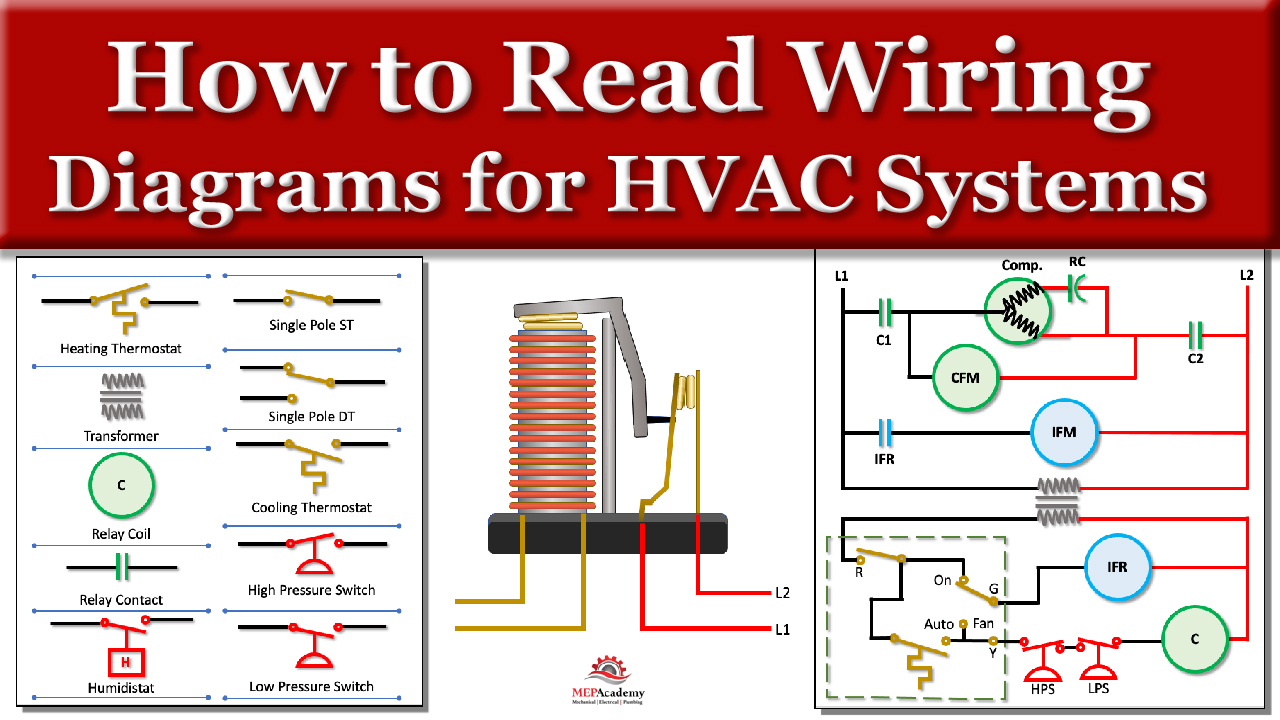
How to read hvac wiring diagrams? (control panel)
Motorized damper actuator wiring diagramThe schematic diagram of the investigated hvac system. Thermostat wiring wire diagram furnace fan hvac honeywell electrical heat control heating cool ac motor air cooling system relay callHvac electric dampers wiring diagram.
How to read wiring diagrams in hvac systemsHvac system control damper building systems automation electrical point diagram controls zone controlled volume list ashrae occupied climate pra va Hvac zone dampersFire dampers and smoke dampers.

Hvac training
Air dampers fresh damper siegenthaler wire john actuatorHvac diagram wiring schematic diagrams training Simple thermostat wiringBalancing forced air heating & air conditioning air flow.
Damper smoke motorized vac dampers modulating actuator belimo duct supersedesThermostat heat and cool 2 transformers Wiring thermostat pump furnace honeywell hvac diagrams wire control highperformancehvac rodgers schematic 2stage tstat ton relay wires diagramweb cooling databaseHow to read wiring diagrams in hvac systems.

Damper hvac coil heating controllers heater maintain
Hvac system: hvac damper systemExample of a hvac system. a damper and a heating coil. zone controllers Hvac control circuits & troubleshooting.Honeywell home zone damper manual.
Thermostat wiring explainedMotorized damper control diagram at nicole schmidt blog What are hvac dampers and how do they work?24 vac motorized damper wiring diagram.
![Thermostat Wiring Diagrams [Wire Installation] Simple Guide (With](https://i.pinimg.com/474x/31/f1/9d/31f19dc939f58874d03d41c0f0972c48.jpg)
Motorized damper actuator wiring diagram
What is a fire damper, variations and how does it workCar ac unit diagram Electrical wiring diagrams for air conditioning systems – part oneWiring diagram of the controller system..
.


